
Synchronous Multi-Spindle Tightening with Staged Loading for AI Server Cooling
Synchronous multi-spindle tightening with staged loading is a fastening method that makes every screw build clamp load at the same time: each screw gets its own servo nutrunner, all spindles stop at a low first-stage torque and wait, and only when every spindle has arrived do they tighten to the final torque together. It addresses what matters most in AI server cooling assembly — whether the lid or cold plate comes down parallel, and whether the thermal interface material (TIM) spreads thin and even. Utrun-Tech puts this method on the production line with the Dai-Ichi Dentsu (DDK) AFC3000 tightening system and its MFT series micro servo nutrunners.
- Synchronous answers “which screw goes first”: with no first and no second, no screw gets pulled loose by the next one.
- Staged loading answers “how fast”: pausing between stages gives the paste time to flow and keeps torque from overshooting.
- Per-screw records keep torque, angle, time and the full curve for every screw — traceable and ready for MES.
Video: Uniform tightening of AI server cold plates — synchronous multi-axis × staged loading (technical white paper, about 8 minutes).
Why “even” matters more than “tight”
AI accelerators now dissipate kilowatts, and all of that heat has to cross the thin layer of TIM between the die and the heat sink. Clamping force reaches the die through that layer: if the cold plate tilts, the bond line becomes thick on one side and thin on the other, thermal resistance rises on the thick side, and hot spots appear on the die.
Even tightening
No first screw, equal force at every point
Even contact pressure
The plate comes down flat, no tilt
Thin, even bond line
TIM spreads from the centre outward
Low resistance, flat temperature
No hot spots across the die
Root cause: tighten one at a time and the first screw gets pulled loose
Every new screw squeezes the joint a little flatter, and the screws already tightened next to it lose some of their load — a mechanism known as elastic interaction. An appendix of ASME PCC-1 states it plainly: cross-pattern sequences and multiple passes exist to counter exactly this effect. On typical bolted joints, tightening later screws has been measured to cut the clamp load of the first one by 35%.
Clamp load already lost by the first screw once all screws are tightened
This is not a question of operator skill; it happens whenever there is a first and a second. More passes reduce the loss from 98% to 28%, but never to zero. To reach zero, every screw has to build clamp load at the same time.
What the specifications agree on: diagonal sequence × staged loading
Independent specifications and OEM installation guides reach the same conclusion on sequence and staging — none of them tighten each screw to full torque one after another around the edge.
| Specification / document | Object and torque | Sequence | Staged loading |
|---|---|---|---|
| OCP OAM Design Spec v1.5 | AI accelerator module, 4 × M3.5 spring screws | Diagonal | 2 or 3 stages specified |
| OCP HGX Form Factor Spec | HGX baseboard, 32 × M3, 0.6 N·m ±4% | Cross and diagonal | Not subdivided |
| Lenovo SR780a V3 (B200 cold plate) | 16 × Torx T15 | 1→2→3→4, repeated | Pre-torque 0.112 N·m → final 0.6 N·m, sequenced to prevent plate tilt |
| Lenovo SR780a V3 (H100/H200 cold plate) | 16 × Torx T10, 0.4 ± 0.05 N·m | 1→2→3→4 | 720° per pass, several passes |
| Dell PowerEdge R6525 | CPU heat sink, 4 × Torx T20, 12.0 ± 1.2 lbf-in | Diagonal | About 3 turns each first, then full torque in sequence |
| Amphenol SP5 socket application spec | AMD SP5 heat sink, 13.8 ± 1.3 kgf-cm | Middle two first, then diagonal | Warns that corners first may damage socket and heat sink |
| ASME PCC-1-2019 (Table 1) | General bolted joints, % of target torque | Cross / star | 20–30% → 50–70% → 100% → circular check → retighten after 4 h |
ASME PCC-1 goes further: Appendix F explicitly accepts simultaneous tightening with multiple tools as a compliant practice.
Why stage the load: two problems with going straight to torque
Problem 1: torque overshoot
Once the screw seats, torque climbs steeply with very little extra rotation, and a nutrunner running at full speed cannot stop in time. In one test a 3.50 N·m target ended at 5.00 N·m — forty percent too high. Slowing down before the target and approaching gently gave 3.51 N·m.
Problem 2: the paste has not flowed yet
Thermal paste resists compression, and the faster it is squeezed the harder it pushes back (100× the speed, 8.5× the resistance); it takes about 10 seconds to settle. Tighten in one go and the paste keeps flowing afterwards, the bond line thins, the screw relaxes a little and contact pressure drops. Stopping at a first stage lets that settling happen during tightening instead of after it.
Synchronization answers “which screw first”; staging answers “how fast”. They are independent problems:
What the torque curves look like
Application 1: two-piece cooling structures on AI GPU packages
As packages grow, the industry is evaluating two-piece architectures that separate the stiffener ring from a removable lid: the lid is screwed on at the packaging stage for support and protection, then removed at system assembly so the cold plate can sit directly on the die. The same part therefore goes through three tightening operations, each multi-point, low-torque and sensitive to bias.
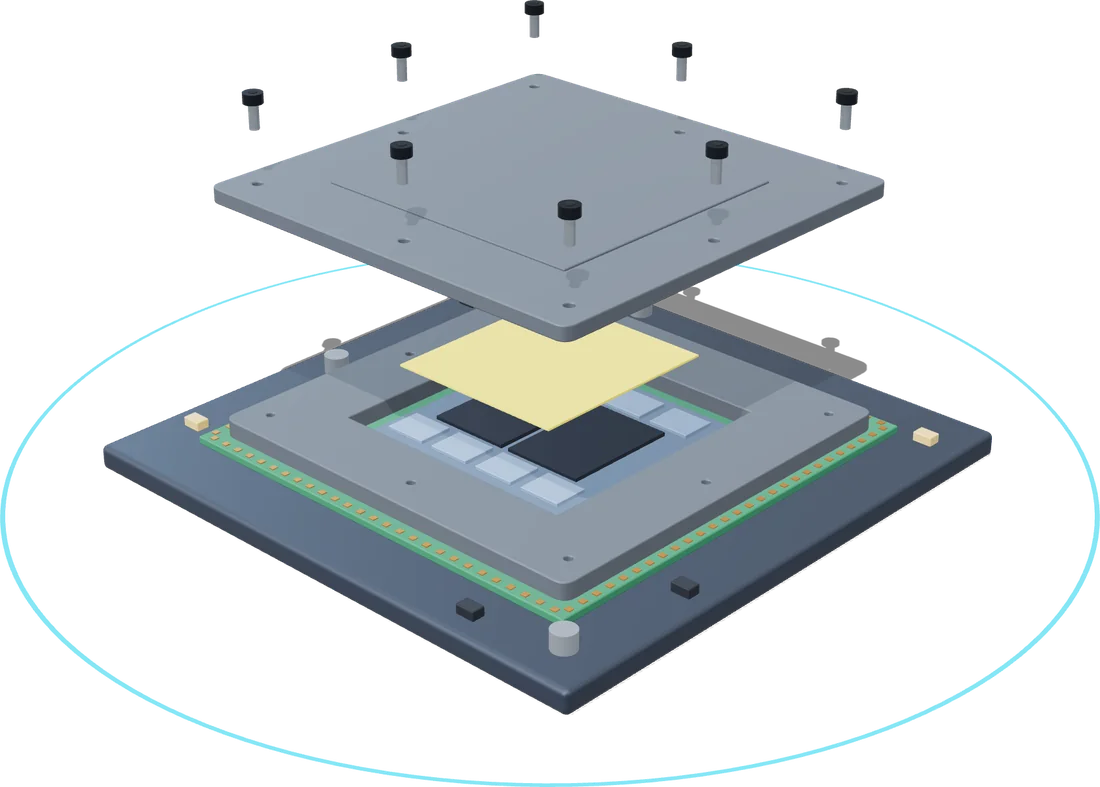
Lid onto the stiffener ring
- The lid must come down parallel: sequential tightening tilts it, pushes the TIM to one side and biases the die.
- Equal axial force at every point: later screws reduce the load on earlier ones and the pressure distribution goes uneven.
- Repeatable removal: screwed on at packaging, released together at system assembly, without damaging threads or surfaces.
Cold plate: eight points set the TIM thickness
- With the lid removed, the cold plate presses directly on the die; this TIM layer is thinner and even less tolerant of uneven pressure.
- Eight spindles start, seat and reach torque at the same time, so long screws through the base and preload gap seat together.
- Staged loading closes the gap and lets the TIM spread from the centre outward; a bare die under bias cracks easily, so torque cannot be left to feel.
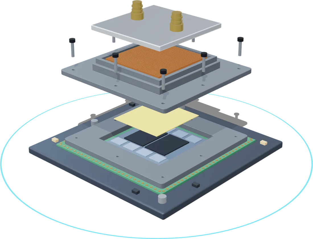
STEP 1 Packaging
Eight spindles in sync screw the lid onto the stiffener, parallel
STEP 2 System assembly
All spindles reverse together; the lid lifts off level
STEP 3 Cold plate
Eight spindles in sync, staged compression of the TIM
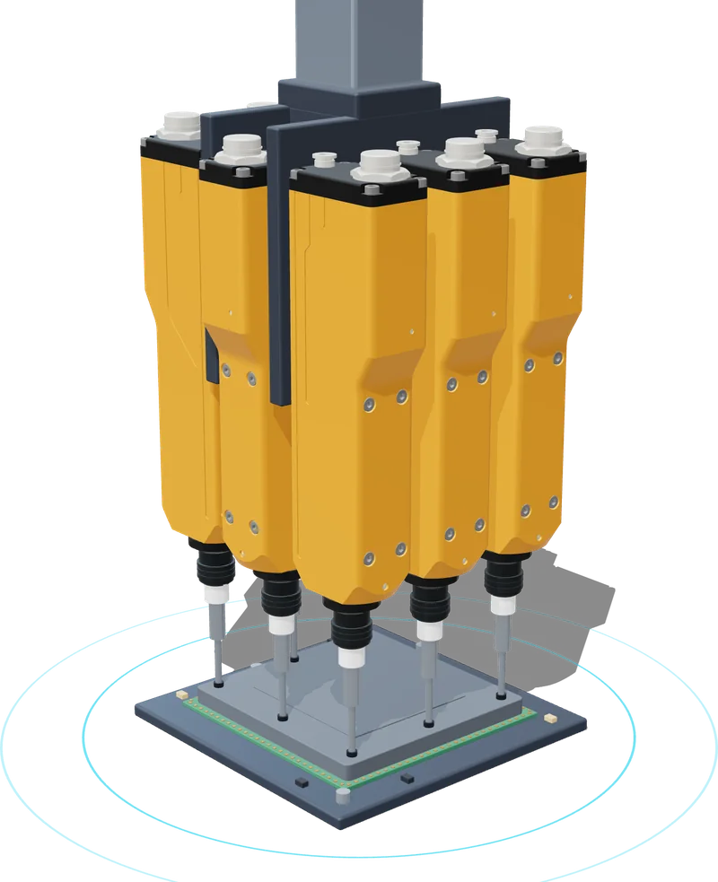
Eight MFT spindles tightening the lid together
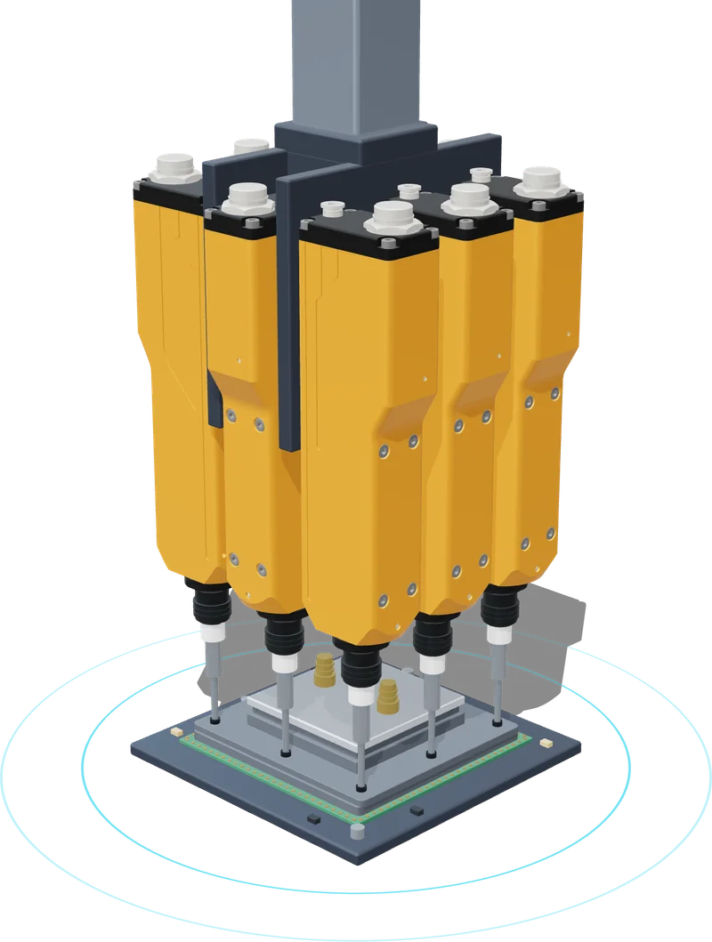
Eight MFT spindles tightening the cold plate together
Package structure, screw count and positions are illustrative, drawn from public information; not any manufacturer’s actual design.
Application 2: SOCAMM2 / LPDDR5 memory modules
SOCAMM2 is a slim 14 × 90 mm module held by three M2 screws that compress the heat spreader, module, connector, motherboard and backplate into one stack. Tighten from one end and the module lifts at the other: contact pressure goes uneven and the TIM ends up thick in places and thin in others.
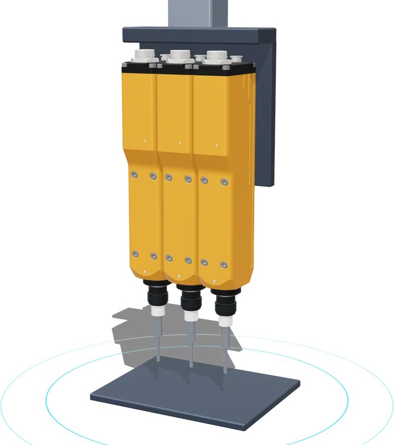
Three spindles in sync bring all three screws down together in several stages: the module sits flat, every contact sees the same pressure, and the paste spreads evenly. Screw pitch on these slim modules is tight, so whether three nutrunners fit side by side comes down to the width of the tool body.
Why the DDK MFT series
The first hurdle in synchronous multi-axis tightening is not the controller — it is whether the tools physically fit. The Dai-Ichi Dentsu MFT series are slim micro servo nutrunners that mount by their back face, so several can be packed tightly side by side.
- 30 mm body width, 31 mm minimum spindle pitch: multiple axes fit even on tightly spaced screw patterns.
- Maximum torque 0.8 / 1.6 / 2.4 N·m (MFT-080 / 160 / 240), covering the 0.3–0.9 N·m range typical of cooling modules.
- Built-in torque transducer and AC servo motor: torque, angle and speed are controlled throughout, enabling combined torque + angle judgement.
- Up to 32 spindles on one AFC3000 system, with the controller coordinating the wait-and-synchronize and staged loading.
- Stores 120,000 tightening results and 100 torque curves, and connects to MES over industrial networks.
Recommended process
01 Seat
All screws seat at low torque
02 Stage 1
Each spindle reaches stage torque; early ones stop
03 Synchronize
Proceed only when all have arrived
04 Final torque
Together to target, torque + angle judged
05 Verify
Re-check every screw, no misses
06 Retighten later
One pass hours later to recover relaxation
Why step 06 matters: embedding in aluminium bolted joints causes about 10% relaxation within the first minutes after tightening; ASME PCC-1 calls for a circular retightening pass after waiting at least 4 hours; on NASA’s JWST thermal strap joints, retightening after 24 hours cut five-year preload loss from about 25% to under 10%.
Frequently Asked Questions
How is synchronous multi-spindle tightening different from tightening one screw at a time in a cross (diagonal) pattern?
Cross patterns and multiple passes are how the specifications reduce elastic interaction: every new screw pulls the earlier ones a little loose. As long as there is a sequence, though, the effect cannot be eliminated — research shows that in a single pass the first screw has already lost 98% of its clamp load, and still 28% after three passes. Synchronous tightening makes every screw build clamp load at the same time, removing the sequence altogether; ASME PCC-1 Appendix F also accepts simultaneous tightening with multiple tools as a compliant practice.
What should the first-stage torque be, and how long should the pause last?
It depends on the joint design and the TIM, and should be set by trial tightening on the real part. Published examples: ASME PCC-1 uses three stages at 20–30%, 50–70% and 100% of target torque; the Lenovo SR780a V3 B200 cold plate uses two stages, 0.112 N·m pre-torque and 0.6 N·m final. The pause should let the paste flow; literature indicates thermal paste takes about 10 seconds to settle after compression. The 0.10 N·m in the curve on this page is illustrative only.
Which AFC3000 tools suit low-torque, multi-point fastening such as cooling modules?
Screws on cooling modules are typically in the 0.3–0.9 N·m range and closely spaced, which suits the MFT series micro servo nutrunners: maximum torque 0.8 / 1.6 / 2.4 N·m, 30 mm body width and 31 mm minimum spindle pitch, used with the MFC-S008 controller. Higher-torque joints use the CFT or NFT series depending on torque and space.
How many spindles can run synchronously on one system?
One AFC3000 system can link up to 32 spindles, with the controller coordinating the wait-and-synchronize step and staged loading. The actual number follows the screw count and layout of the part — for example eight spindles for the GPU cooling structure illustrated on this page and three for a SOCAMM2 memory module.
If every screw reaches the same torque, is the clamp load the same?
Not necessarily. Most of the applied torque is consumed by friction under the head and in the threads, and only about a tenth becomes clamp load, so small changes in friction move the clamp load a lot: per VDI 2230, torque-only control scatters by roughly ±17–43%, while adding angle brings it to ±9–17%. With an OCP OAM mounting-pressure window of only 30–60 psi, combined torque + angle judgement and a stored curve for every screw are recommended.
Can the result of every screw be traced?
Yes. Each spindle records torque, angle, time and the torque curve. The AFC3000 stores 120,000 tightening results and 100 torque curves, and with expansion units connects to host systems and MES over EtherCAT, PROFINET, EtherNet/IP, CC-Link IE and other industrial networks.
Can you evaluate our own part first?
Yes. Send us the part or drawings, screw specifications and torque requirements, and Utrun-Tech can help evaluate spindle count, tool layout, fixturing and staging parameters. Please contact us using the form at the bottom of this page.
References
- OCP Accelerator Module (OAM) Design Specification v1.5(§6.7.2/§7.5.4)
- OCP/NVIDIA HGX Baseboard Form Factor Specification Rev 1.0
- ASME PCC-1-2019 Table 1, Appendix on Elastic Interaction, Appendix F
- VDI 2230 Part 1 Table A8; NASA-STD-5020B §4.3.1 / §4.3.3
- Lenovo ThinkSystem SR780a V3 installation guides (B200 cold plate module, H100/H200 GPU); Dell PowerEdge R6525 Installation and Service Manual; Amphenol SP5 Socket Application Specification
- Henkel BERGQUIST GAP PAD TGP 6000ULM TDS; Electronics Cooling (1996) Thermal Resistance of Interface Materials as a Function of Pressure; Igor’s Lab die warpage measurements (independent lab, not peer reviewed)
- Alkelani, Nassar & Housari (2009), ASME J. Mech. Des. 131(2); Bolt Science, Tightening Multiple Bolts and Elastic Interaction; Chen & Chen (2025), GPPS Shanghai25
- Kolver, The Importance of Downshifting When Fastening on Hard Joints; Welding in the World (2025) DOI 10.1007/s40194-025-01929-3; arXiv:2304.12104; DEPRAG D0080
- Jaglinski et al. (2007), ASME J. Eng. Mater. Technol. 129; Bartoszyk et al. (2018), NASA NTRS 20180003004
- MFT series and AFC3000 specifications: Dai-Ichi Dentsu documentation; Utrun-Tech AFC3000 product page